| |
|
 |
 Profile Profile
Our family of products consists of: Temperature related instruments like Indicators, Single set point controllers, Two/Four set point controllers, transmitters, Temp. Sensors, Scanners Flame Proof Indicators and Controllers, Maxthermo make PID controllers etc. and general purpose instruments like Timers, Counters and Length meters, Cyclic Timers. In addition, we have developed customized instruments like, Temperature controller and Soak timer coupled in one unit (Temp-Time), RH -cum-Temperature controller, Process controller Profile Controllers, etc.
|
|
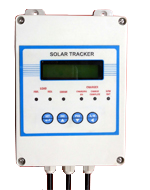
Solar Tracker Controller |
|

|
| Specifications : |
| Tracker : |
| Tracker Principle |
: |
controls azimuth angle according to astronomical sun positioning |
| Tracking axis |
: |
single axis |
| Size |
: |
170mm x 120mm |
| Input voltage |
: |
12VDC |
| Enclosure |
|
IP65 ABS grade |
| Termination |
: |
IP65 graded ABS glands – 2 nos |
| Output |
: |
12V output to actuator up to 20A load |
| Resolution |
: |
0.1 degrees |
| Axis angle |
: |
settable up to +/‐ 60 degrees |
| Control action |
: |
automatic closed loop using inbuilt inclinometer for angle feedback |
| Display |
: |
16 x2 LCD display |
| Timing |
: |
Inbuilt using highly accurate RTC with independent battery backup |
| Accuracy |
: |
< +/‐1 degrees |
| Safety features |
: |
a. Reverse polarity protection |
| |
|
b. Over current protection |
| |
|
c. Voltage spike suppression |
| |
|
d. over current drain protection against mechanical failure of the actuator
system * |
|
|
| |
** The unit has an inbuilt time limit for the on time of the actuator fixed at approximately 2.5 minutes.
This is to ensure that if the actuator fails to move the panel to the required target angle for more than
2.5 minutes, the unit turns off the actuator load to preserve battery life and indicates “mech failure” for
3 seconds on the LCD display before skipping to the next target angle. |
| |
|
| |
| Charger : |
| Input |
: |
Photovoltaic (PV) Panel or equivalent DC voltage source |
| Output |
: |
To 12V,7.5AH Sealed Lead acid Battery |
| Charging protocol |
: |
3-stage intelligent CV/CC charging profile |
| Boost Voltage |
: |
14.4V DC |
| Boost current limit |
|
1.0A |
| Equalisation voltage |
: |
14.4V |
| Equalization threshold current |
: |
0.01C (0.07A) |
| Trickle voltage |
: |
13.5V |
| Trickle current limit |
: |
0.4A |
| Low battery threshold |
: |
10.8V |
| |
Principle of operation : |
| Tracker: |
The single axis tracker is based on an internal dynamic calculation of the solar sunrise and
sunset time using the current real‐time and date from its inbuilt RTC. After this data is achieved,
it calculates the target angle of the panel and controls the actuator load to achieve this angle.
This control action is repeated for every specific time interval from sunrise to sunset. Note that
this unit does not depend on the time the actuator is ON but instead tends to turn the panel to
the correct angle. This ensures that even if there is any deviation of the panel angle at any point
of time due to external intervention OR through the manual mode of the unit, the unit will
recover the panel automatically in the next control cycle. The LCD display shows the various
important parameters like Time, Date, Target ‐angle/Target time,etc.( discussed in the next
section). The unit also provides setting of various parameters to the user through four keys on
the front panel thus making the unit extremely flexible and can be adapted by the
user for different environments much easily. |
| |
| Charger : |
The inbuilt charger in the tracker unit is based on a three stage charging protocol which
involves a boost stage, a equilisation stage and finally after the battery is completely charged, a
trickle charge stage. If the battery is detected to fall below a low battery threshold, the output
to the tracker load (actuator) is automatically disconnected and if sufficient PV voltage is
present the boost charge stage is initiated. This quickly replenishes the energy to the battery
without overcharging it by continuously monitoring the charging voltage and current to the
battery. The equalization stage is introduced to give the battery sufficient energy after the
peak voltage is achieved. Here the charging current is monitored until it drops to 0.01C of the
battery. Now the battery is fully charged and the trickle stage is initiated. This ensures that the
battery is continuously kept in a charged state and internal losses are compensated. |
| |
| Programming modes of the unit : |
| 1. Normal Mode: (Read only) : |
This is the default display mode of the unit on power ON. It scrolls the following sets of
important data to the user to confirm the proper functioning of the unit.
a. Real‐ time and present angle for 22 seconds.
b. Sunrise and sunset time for 5 seconds.
c. Next target angle and time for 5 seconds
d. Load current and current date for 5 seconds.
e. Back to a. |
| |
| 2. Manual mode: |
To enter this mode, press and hold SHIFT key for 8~ 9 seconds. The display will initially show
“Manual mode entering…” for 2 seconds and then continuously show the actual angle of the
panel in the bottom row. Now the user can manually inch the panel in the forward OR reverse
direction by pressing the INC and DEC key respectively. To exit this mode, just press and hold
SHF key again for 3‐4 seconds until the message “manual mode exiting…” pops on the display.
This mode is recommended only during installation or general troubleshooting of the
mechanical structure of the panel and unit should be exited to the normal mode once work is
over. |
| |
| 3. Program mode: |
This mode is used for setting the various system parameters of the unit like time,date,time
interval,etc.
To enter this mode, press and hold SET key for 3‐4 seconds. To change the parameters, use the
SHF key to move highlight (blinking)within the parameter and then to increment /decrement
the value of the blinking value, press INC and DEC key . To save the present parameter and
move to the next parameter just press momentarily the SET key again. The various parameters
and their functions are as below:
a. “set the date”: This is the current date of the unit in dd‐mm‐yyyy format
b. “set PV threshold” : This parameter determines the minimum PV voltage input required to
Turn on the panel control action during daytime **.
c. “current limit”: This determines the maximum current limit that can be sourced to the
Actuator during movement of the panel. If this limit is exceeded, then
the unit will automatically turn off the output to the load.
d. “time interval”: This determines the periodic time interval in minutes during daytime
when the unit recalculates the next target angle/ target time and tends
Page 3 of 3
to bring the panel to the present required angle. This parameter
increments in steps of 5 minutes from 15 minutes to 90 minutes max.
e. “set the time”: set the real time in hh:mm:ss format.
To come out of the Program mode, press and hold SET key again for 3‐4 seconds. The unit
will revert back to the normal mode. |
| |
| 4. Installation mode: |
This mode is required for calibrating the start position and end position of the panel in sync
with the unit. This ensures that the target angle to be achieved will not cross this limits while
controlling the panel. To enter this mode, follow the following procedure:
Press and hold INC key for more than 10 seconds
The display will show “calibration mode” on the display for 2‐3
seconds and then show “set start angle “ and actual angle on the display. Now inch the
panel to the start position (stow position)using the INC and DEC key and press SHF key
to accept the start angle. A confirmation will be momentarily displayed “ start angle
accepted!” on the display and the display will now show “ set end angle”. Again move
the panel to the required end angle using INC and DEC keys and press SET key to accept
the end angle. A confirmation ”end angle accepted!” will be displayed momentarily
before the unit reverts back to the normal mode.
Note that this mode is required only once during installation of the panel on site and
need not be set again. The start /end angle setting ensures that the actuator is not
pushed to its extreme ends. |
|
|
|